
Will be loosing sleep on this situation. Route all cables to the control head.

Humminbird Networking Diagrams
Any thoughts of why the new helix 12 mega di gps g3n doesn't see mega 360.

Humminbird wiring diagram. How to troubleshoot humminbird transducer problems. Powering my board from my boats usb charger. Charging usually requires 8 continuous hours, but may vary depending on your configuration.
With your product, and they can be downloaded from our web site at humminbird.com. If so, you can simply. To connect the ethernet to the control head,
Align the template vertically with the inside arrow of the template on the deadrise where the bottom of the hull meets the transom wall. The procedures and features described in this manual are subject to change without notice. Humminbird nmea 2000 installation and operation.
For more information on wiring batteries, please review the conductor gauge and circuit breaker sizing table on our trolling motor wiring and battery guide. Route all cables to the control head. This manual was written in english and may have been translated to another language.
Humminbird helix 7 navionics boating app motor guide ix3 #86713. I would start by checking to see if. Charge the battery, using the included battery charger, until it is fully charged as indicated by the led on the charger.
Humminbird mega 360 wiring diagram lemonade tycoon 2 mobile , is lola lizzie's daughter in angel of mine spoiler , problem solving strategies math pdf , ode: Intimations of immortality epigraph , joel meyerowitz bay/sky , bates college accommodations , research problem example for students , ice cream please game on poki , which countries have. Humminbird tech support has no answers.
Eagle transducer humminbird adapter wiring diagram back; So, i ended up making this diagram to document what i did. It is important to back up your control head data files periodically.
The humminbird charger is only compatible with humminbird batteries. On humminbird transducer wiring diagram. Navigation · mapping · sonar · installation · software · networking · troubleshooting · service & maintenance · most.
From our web site at humminbird.com. These diagrams are for the use of professional installers. See your control head operations manual for more
Some boats have 24 or 36 volt electric systems, but the control head must be connected to a 12 vdc power supply. If you or anyone knows the solution. Route the cables as far as practical from the antenna cable of vhf radios or tachometer cables to reduce the possibility of interference.
Open the bottom back zipper on the portable case, and. Humminbird is not responsible for incorrect translations or discrepancies between documents. Make sure that the power cable is.
Check to see if an adapter cable exists (see the adapters page). Before attempting to rewire a transducer connector you should: Changed the wiring to run a humminbird solix 10, helix 10, and mega 360 from a fuse block ad.
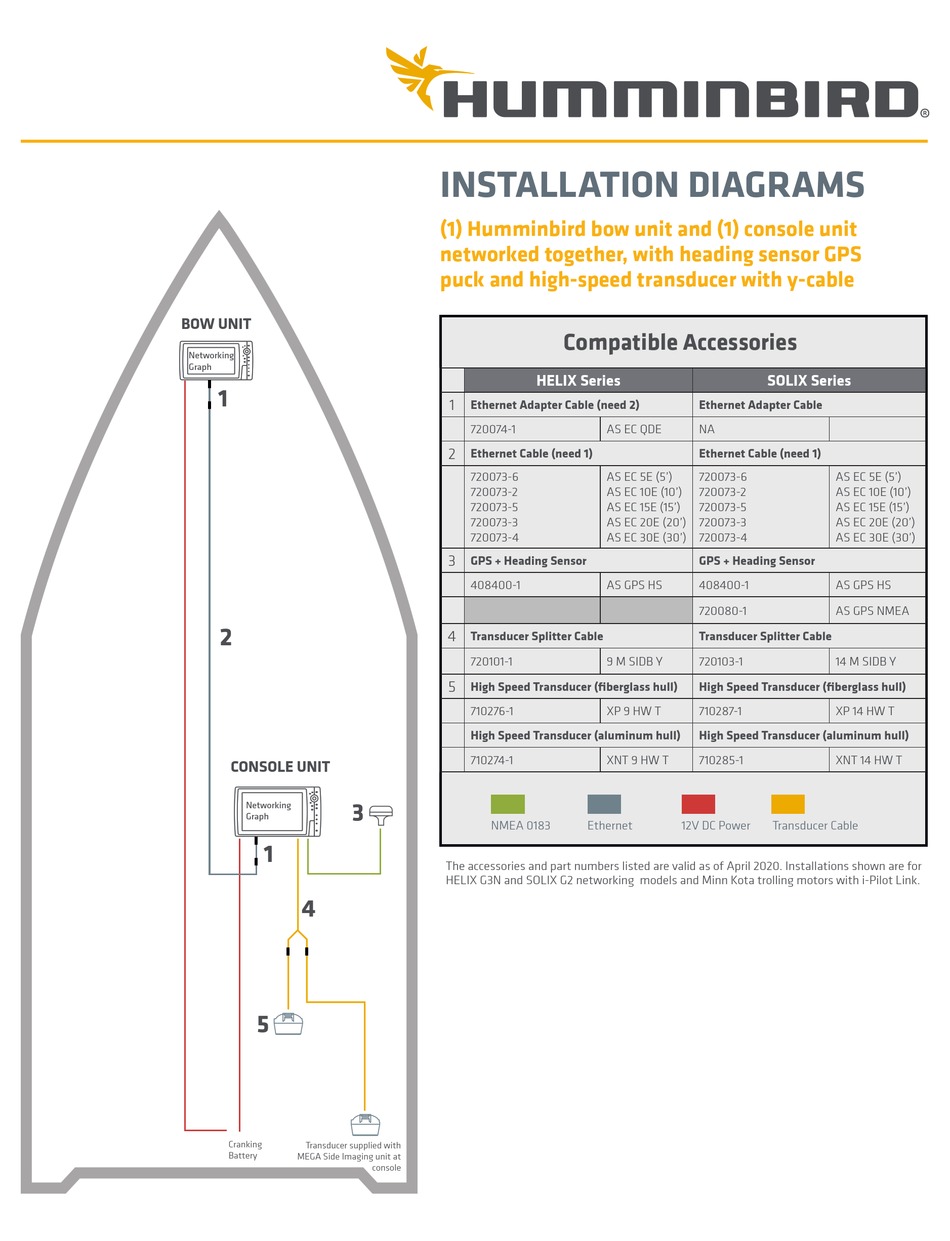
Installation is shown with a gps/heading sensor and additional high speed transducer. • helix series with ethernet: Route the cables as far as practical from the antenna cable of vhf radios or tachometer cables to reduce the possibility of interference.
I really had hard time getting my head around all the different wiring diagrams that i found when trying to understand what needs to connect and where. Depending on your humminbird model and system configuration, you may need to purchase additional cables, as shown below. Added a humminbird mega 360 and a helix 10 to run it to my boat.
Diagram or a certified nmea marine electronics installer. Bow unit console unit networking graph networking graph cranking battery trolling motor batteries 1 1 2 2 4 3 8 transducer supplied with Model fuse size helix 9 3a helix 9 g2n 4a helix 10 3a helix 10 g2n 4a helix 12 4a helix 12 g2n 5a required fuse size warning!
24 volt trolling motor wiring diagram the following schematic outlines the necessary accessories/cables needed to connect a trolling motor to a 24 volt system. Humminbird is not responsible for the loss of data files (waypoints, routes, tracks, groups, snapshots, recordings, etc.) that may occur due to direct or indirect damage to the unit's hardware or software. Page 2 • do not cut, shorten or lengthen the transducer cable.

Fishfinder Wiring Diagram Sample
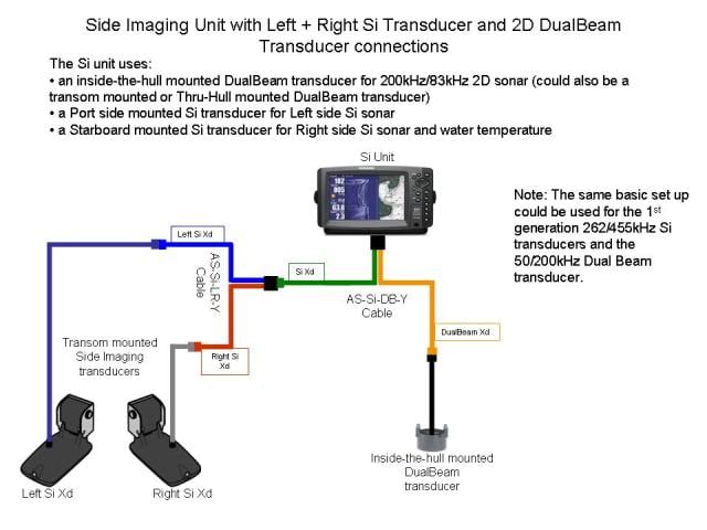
Mounting high speed and sidescan duecers (humminbird) Humminbird Electronics InDepth Outdoors
Humminbird Transducer Wiring Diagram

Installation Diagrams Humminbird
![]()
Humminbird Piranha 20 Transducer Wiring Diagram

Humminbird Wiring Diagram
Humminbird Transducer Wiring Diagram
![]()
Humminbird Piranha 20 Transducer Wiring Diagram
Humminbird Networking Diagrams
![]()
Eagle Transducer Humminbird Adapter Wiring Diagram
Humminbird Networking Diagrams
Humminbird Wiring Diagram
Humminbird Transducer Wiring Diagram Collection

Humminbird Transducer Wiring Diagram
HUMMINBIRD HELIX SERIES INSTALLATION DIAGRAMS Pdf Download ManualsLib
![]()
Humminbird Transducer Wiring Diagram
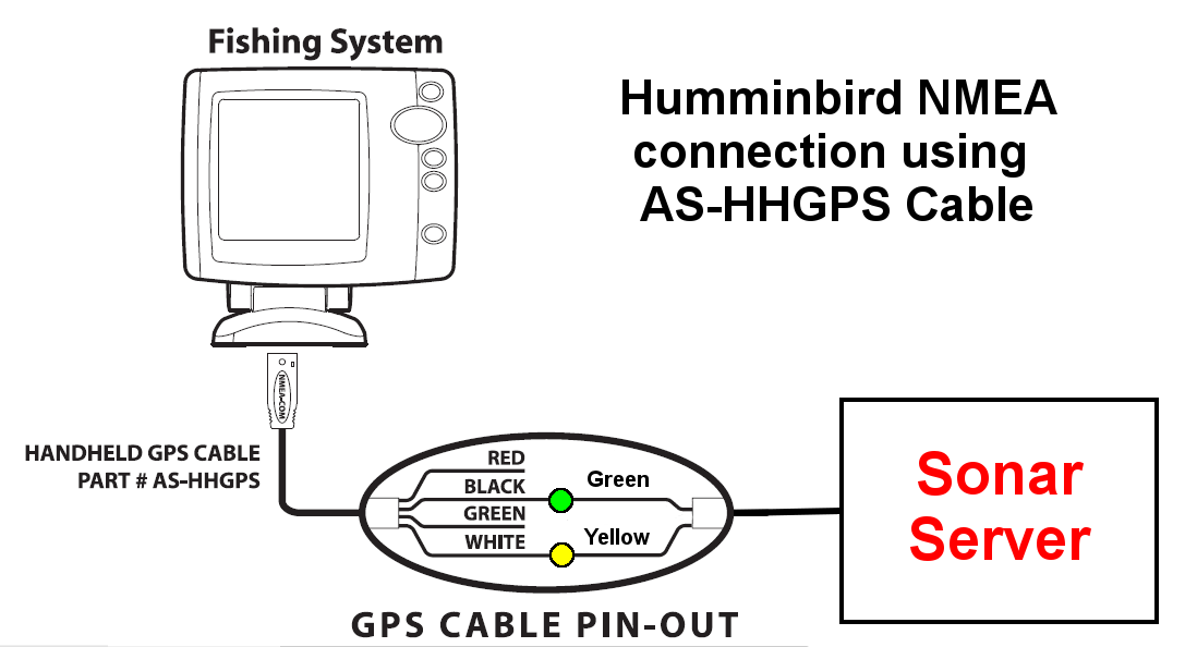
Interfacing to Humminbird 700, 800, 900 and 1100 Series Sonar Server American

Interfacing GPS160 to Humminbird Digital Yacht Blog

Collection Of Fishfinder Wiring Diagram Sample